Background
The aim of this project was to improve design elements of the dashboard on ADL19E (the Adelaide University Motorsport Team’s second electric FSAE race car), with the intention of using the new design on the next generation car.
Figure 1 shows the dashboard on ADL19E; the accumulator State of Charge (SoC) and Temp indicator bars are the focus of this project. These indicators provide the driver with useful feedback on whether adjustments to driving style are necessary to complete the event.

In a nutshell, the old design works by filtering a PWM signal from the ECU to obtain a DC voltage, which is then passed to a Texas Instruments LM3914V linear analog display driver to display the reading on the LED bars. This design suffers from poor noise tolerance and reading instability, likely the result of the PWM signal travelling a reasonable length of unshielded cable near electrically noisy components. In my opinion, it’s a novel solution to a problem where digital communication would be better suited (at least according to what I learnt in second year digital electronics).
Requirements
1. CAN BUS
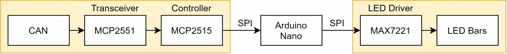
Which leads us to our automotive communicatory lord and saviour, the Control Area Network (CAN) Bus [colloquially called “Canboos”]. I could write an entire post about CAN Bus, maybe I will, but all that’s important at this stage is it’s a simple, robust and relatively fast way for microcontrollers in a car to communicate; we want to use it. Additionally, developing a simple CAN node for the team will be beneficial in future, unlocking more complex design possibilities further down the road.
The new design will communicate to the ECU over CAN. Using a differential signal over a single twisted pair to send digital information, the ECU can communicate reliably in a noisy environment. This is the major improvement over the old design.
2. Digital control
Given the use of CAN, the dashboard LED bars will be controlled by an Arduino Nano. While the Arduino platform may not be most at home in an automotive environment, it’s chosen for the following reasons:
- Availability
The team already uses Nanos in other projects and local supply from Jaycar is readily available in the event that the magic smoke is released. - Speed
The Arduino Nanoruns at 16MHzis going to have a quick development cycle, preferable as I don’t have a lot of time outside of studying for my degree and there are other projects to do on the team. Plenty of libraries are freely available to help get things working as soon as possible. - Accessibility
I’m not going to be on the motorsport team forever. At some point, someone else may have to modify or clone the firmware and I don’t know if they’ll have an electronic background (I hope they do). Arduino is easy enough for a new team member to pick up.
3. SoC and Temp
The new design will display the same information as the old design, the SoC and Temp as reported by the car’s ECU. The team has determined that only displaying key relevant information is the most beneficial for the driver.
4. Visible in daylight
The displays need to be visible to the driver in bright daylight.
Design
Concept
After establishing the broad requirements, two concept designs were brainstormed and then mocked up in Photoshop. Figure 2 shows the first concept, using 20 discrete digital LEDs like Adafruit’s NeoPixel range. This would allow for a simple circuit design, as the LED drivers are contained within the LEDs themselves and communicate over a chained link.
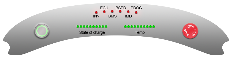
Figure 3 shows the second concept, using the same type of LED bar display as the old design. Each LED bar is simply 20 bog standard individually driven LEDs combined into a single THT package.

Concept two was chosen on the basis of reliability and resolution. Should any one of the digital LEDs fail in concept one, the entire LED display may be compromised. The LED bars are able to fit more LEDs in a similar area, allowing higher resolution feedback to the driver.
In regards to cost, buying twenty through hole NeoPixels came out to roughly $40 AUD, whereas buying two LED bars is about $15 AUD. However, pricing out the supporting driver components required for the LED bars brought the two concepts to roughly the same price.
Prototype
CAN Communication
In my experience, getting a basic working model is always a great first step if you’re unsure about where to start. At the beginning of this project I had practically zero experience with CAN, so I decided to purchase a few of these cheap CAN modules to try and cobble something together. If you’re looking to buy some yourself, they’re usually a few dollars each on AliExpress, eBay, or your preferred electronics hoarding enabler of choice.
There are plenty of great tutorials available online which go through using these modules with Arduino. Within about 30 minutes, I was able to get an Arduino sending an analog voltage reading over CAN, with the other receiving the value and spitting it out onto the serial port.
As an aside, one issue that kept cropping up for me was that the crystal frequency was not the same on all of my modules, with some parts being 8MHz and others 16MHz. This caused the CAN bitrate to double/halve depending on the settings applied in the Arduino sketch.
LED Driver
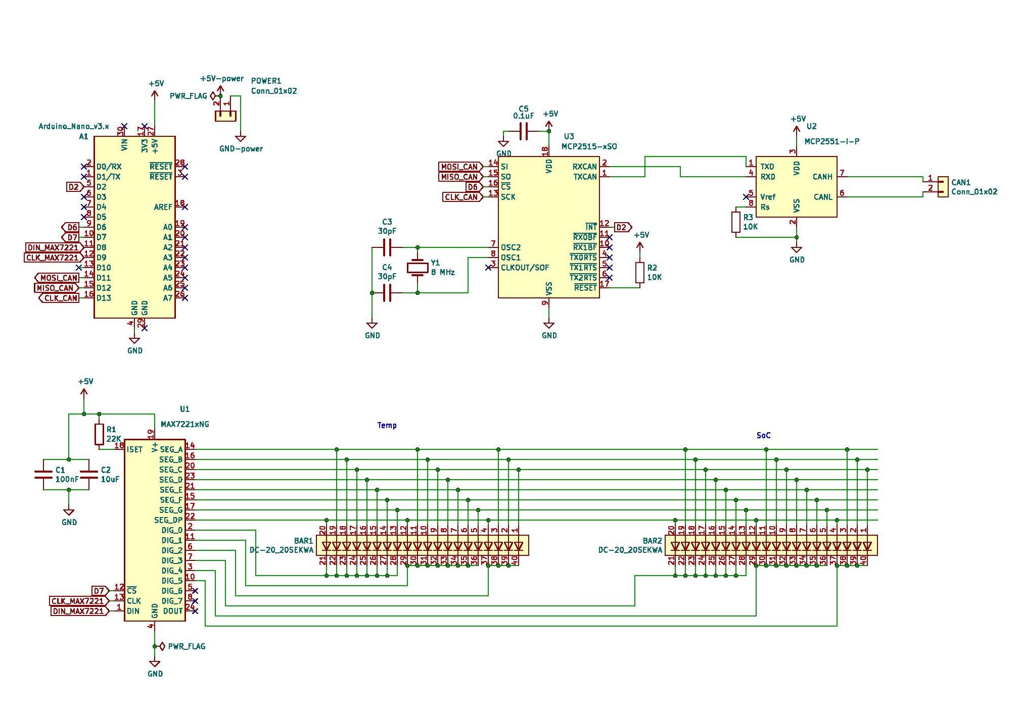
After doing some exploratory research, I settled on using a Maxim MAX7221 LED driver. The 24 pin DIP is well documented and there are a number of libraries available for use with Arduino. The MAX7221 is capable of driving 64 LEDs, more than enough for this project.
There doesn’t seem to be a common development board for the MAX7221, so I ordered the components for a reference circuit in the LedControl documentation and datasheet. These parts would also be used in the final product, provided the circuit works and I don’t break anything.
Below is a short demo reel of the LED driver in action.
Integration
Once I was able to get the two parts working separately, it was fairly straightforward to integrate everything into one Arduino sketch. The video below demos sending two analog voltage readings over CAN and displaying them on the LED bars.
Final Design
Once I’d worked out a few of the bugs, the dashboard LED display looked a little something like Figure 6. It was fairly simple and worked pretty well. The response of the display was quick and it was bright.
PCB
Having a working prototype on a breadboard was great, but I couldn’t tape this mess to the car; I needed a PCB. Full disclosure, I had never designed or made a PCB before, so this was a significant learning experience for me.
Once again I had no idea where to start. Other members of the team had used KiCad in the past, so I set about learning how to use the software. Thankfully, John had created a 33 part comprehensive video series on how to use KiCad (and more) on YouTube (embedded below). This playlist was a great starting point in learning KiCad.
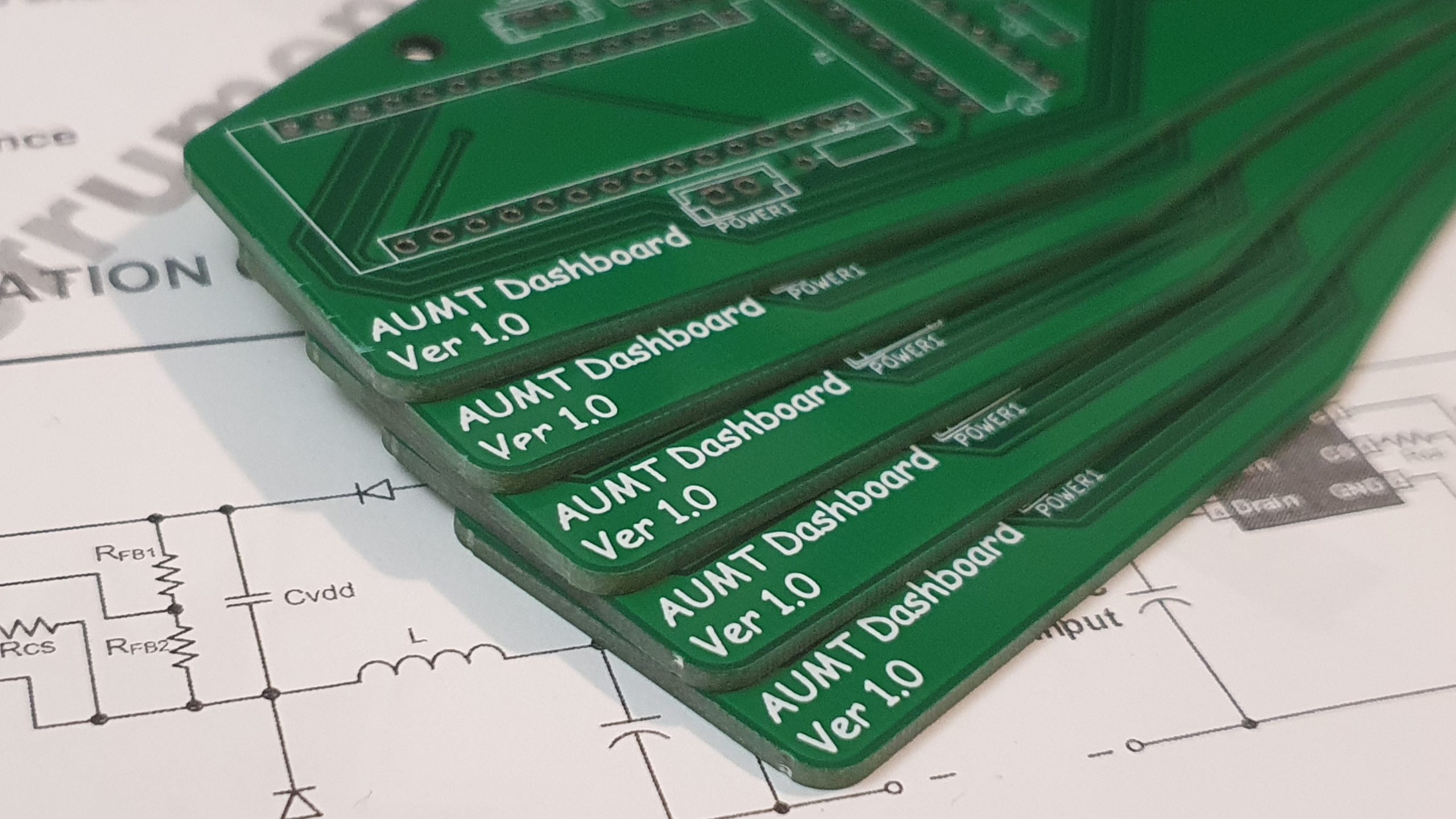
Manufacture
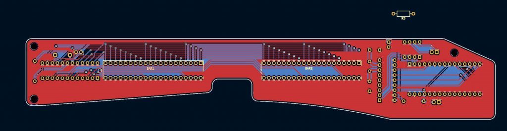
Ordering five boards from JLCPCB cost $7.90 AUD, not including shipping. They turned out pretty great!

In an afternoon I was able to transfer all the components from the breadboard to the PCB (video below). At this point I realised I neglected to build up the CAN components on the breadboard, as I was using the reference design. Upon doing so I discovered I was missing a pulldown resistor on the CAN transceiver which was missing on the board. Luckily that was the only issue and could be easily solved by bodging the required resistor onto the back of the board. I updated the schematic for future reference.
Testing
Hooking up the board to 5V and CAN from the integration testing setup, I was able to receive the voltage reading over CAN and display it on the LED bars! Further testing in the car itself proved successful, with the ECU being able to control the number of LEDs on each bar. The video below shows the result of me turning a potentiometer roughly in time with the top gear theme.
Lessons Learned
1. Footprint clearance
It wasn’t a major issue, but the footprint for the two JST connectors I used in KiCad was incorrect. It was close enough that there was no impact during manufacturing, but I should have checked this during the design phase.
2. CAN resistors
CAN requires two 120Ω resistors on either end of the bus to prevent reflections and keep the bus from floating. I neglected to design one into the dashboard PCB, resulting in the abomination seen in Figure 10, where the resistor is soldered directly to the pins of the CAN connector.

Conclusion
The dashboard project was my first somewhat complex encounter with electronics design. Most of my Arduino experience in the past had involved modules with nicely defined inputs and output, well organised documentation. Designing the dashboard was a great learning experience, especially the discrete circuit and PCB design.
I will try to remember to post some more pictures of the final product once it’s integrated into the car.